|
I am going to document the daily install of my new Trio Avionics EZ Pilot and EZ2 altitute hold with vertical speed http://www.trioavionics.com
. The harnesses used are my original panel harness and the new altitude hold harness made by Steinair, http://www.steinair.com
. I would seriously, and without reservation, recommend Steinair. I guess you will also get a sneak preview of my carbon
fiber panel to go with the rest of the "Black Magic" theme.
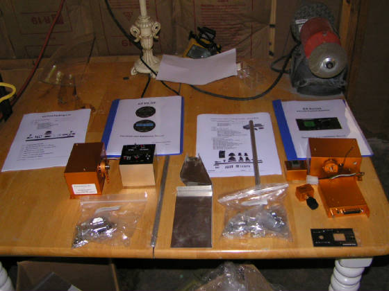
The package has arrived. I have separated the parts into altitude hold on the right, autopilot on the left. It is a very
clean setup and I am impressed with the quality of each of the separate parts. The servos are robust but don't seem to weight
as much as I had anticipated, a good thing. The pushrods even have one female insert for the rod end bearings with the other
side open for cutting to length, nice touch. I haven't read the plans yet but plan to start around 3PM eastern time.
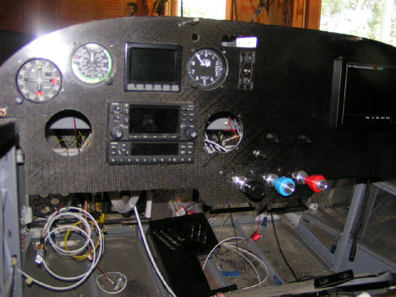
Kind of a fuzzy shot of my carbon fiber panel. The autopilot head will go in the vacant left hole. I am going to install
it first just so I can see where I have space to install the altitude hold units. The altitude hold units are two separate
parts and do not have to be side by side. We will see............any thoughts folks?
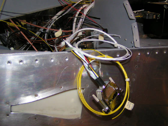
This is the EZ Pilot harness connection coming out of the 430 into the Trio. This is a very small example of the quality
of work performed by the guys, and maybe gals, at Steinair. These people are definitely one of the "highly recommend"
group. I'll post some shots of their altitude hold wiring harness tomorrow when I get it UPS. Off we go to get some work
done. Thanks Stein!!!
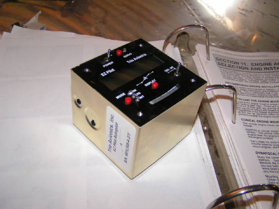
This the Trio autopilot head. It measures 3.25 inches square. The hole are standard spacing. Be careful in drilling your
holes, as this unit is very close. The face is flush and does not have a protruding ring so the hole in your panel is seen.
I'll polish up the hole edges. BTW, this is a very light weight unit.
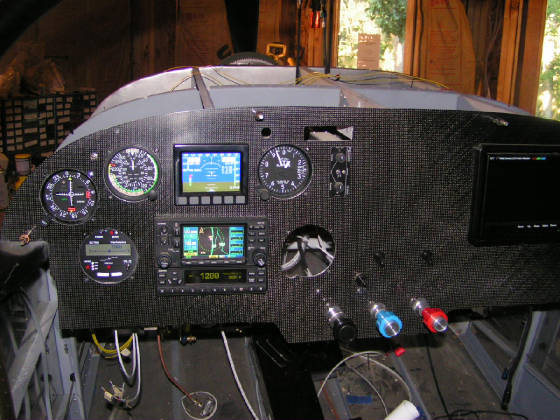
Using the Steinair harness it was a simple matter of attaching ground and GPS data ground with power to the buss. The unit
has it's own switch so there is no need for a single throw switch. There is a ground momentary servo power interupt I need
to put on the panel. My current thoughts are to install it somewhere around the throttle. As you can see on the panel, my
right hand is going to be busy, no big deal though. Anybody got any thoughts on that? Yes, that is a 7" LCD screen on
the right with the DVD player mounted behind the panel. Anybody for in flight movies.............before anyone asks, the
square hole in the middle top is a traffic avoidance system wired through the intercom.
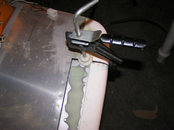
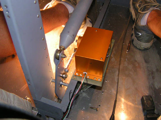
OK, time for the servo install. First thing you need to do is clamp your elevator in the neutral position. This places the
bellcrank in the correct orientation for what follows.
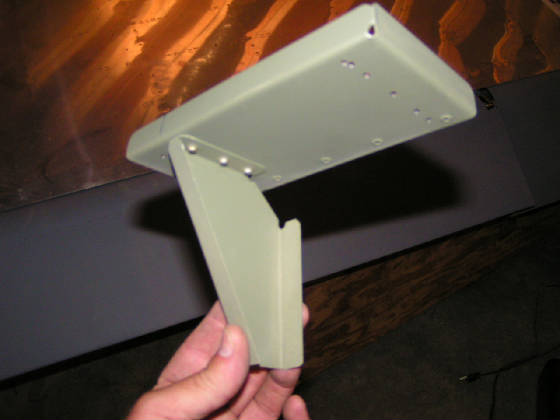
The first thing you do is assemble the servo tray. It consists of the bottom plate and angle bracket which will rivet to
the bottom fuselage elevator bellcrank support. I dimpled five rivet holes for 4-5s and used 4-4s to attach the bottom to
the angle brace. The angle brace at the length provided from Trio places it near the bellcrank pivot point. I followed Sam's
advice and moved it reward on the bottom. In doing so, I had to trim a little off the bottom of the angle as the fuselage
support (rib) gets smaller as it goes aft. I went with the reasoning the radius bend at the rear added enough rigidity to
move the angle support more forward than middle but not flush with the front........man, that was a long explaination for
probably nothing. Anyway, you will be able to drill the tray flush with the passenger side of the angle........see next picture.
Yes, there is an "extra" hole in the picture...don't ask.
I don't need to say this, but be sure and countersink the angle.
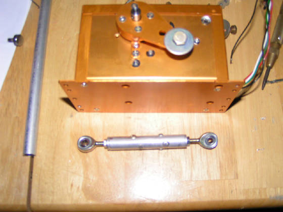
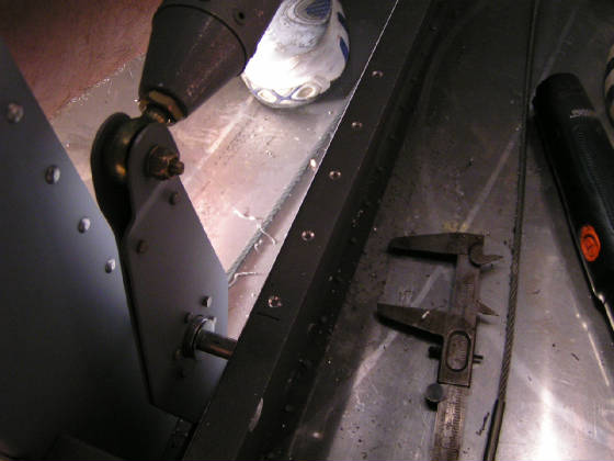
One little pushrod. I left the servo in the pic so you would have a reference as the actual size.
|